MAP Tutorial - Create Workflow
Section author: Hugh Sorby
Note
MAP is currently under active development, and this document will be updated to reflect any changes to the software or new features that are added. You can follow the development of MAP at the launchpad project.
This document details takes the reader through the process of creating a workflow from existing MAP plugins. Having a read through the MAP Features Demonstration is a good way to become familiar with the features of the MAP application.
Getting Started
To get started with MAP we need to create a new workflow. To do this we use File ‣ New ‣ Workflow menu option (Ctrl-N shortcut). This option will present the user with a directory selection dialog. Use the dialog to select a directory where the workflow can be saved. Once we have chosen a directory the step box and workflow canvas will become enabled.
To create a meaningful workflow we will need to use some external plugins. To load these plugins we will use the Plugin Manager tool. The Plugin Manager tool can be found under the Tools menu. Use the Plugin Manager to add the directory location of the MAP Plugins. After confirming the changes to the Plugin Manager you should see a few new additions to the Step box.
Creating the Workflow
To create a workflow we use Drag 'n' Drop to drag steps from the Step box and drop the step onto the workflow canvas. When steps are first dropped onto the canvas they show a red cog icon to indicate that the step is not configured. At a minimum a step requires an identifier to be set before it can be used.
Drag the steps Image Source, Data Store and Automatic Segmenter onto the workflow canvas. All the steps will show a red cog, except the 'Automatic Segmenter', step this indicates that the step needs to be configured. To configure a step we can either right click on the step to bring up a context menu from which the configure action can be chosen or simply click the red cog directly. See the relevant section for the configuration of a particular step.
Note
When configuring a step you are asked to set an identifier. The identifier you set must unique within the workflow and it must not start with a '.'.
Configuring the Image Source Step
The Image Source step requires a location. This location contains the images to import. The location may be a directory on the local hard disk or a workspace on PMR. Here we will show how to configure the Image Source step with images that have been stored in a workspace on PMR.
First each step requires a unique id. The id is used to create a file containing the step configuration information. This id for the Image Source step is used to create a directory under the workflow project directory. In the identifier edit box enter a directory name. Once a valid identifier is entered the red highlight around the edit box will be turned off.
Next change to the PMR tab and we will see an ellipses button for bringing up the PMR tool dialog. You need to register the PMR tool to access certain webservices the details on how to do this are available here. The remainder of this tutorial will assume you have setup access to PMR properly. In the search box of the PMR dialog we need to enter the search term 'blood-vessels'. The result of the search should look like the image below.
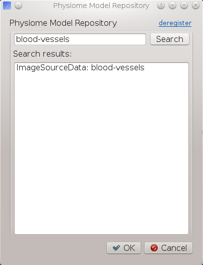
Select this entry in the search listing and click 'Ok'. The selected PMR workspace will be downloaded in the background. When the download is finished the red cog icon will disappear. If the download is not successful a dialog will appear to inform you of the error.
MAP is not setup to work with streamed resources so we must download the workspace from PMR.
Configuring the Point Cloud Step
Configuring the Point Cloud step is trivial at this time. This is because the step only requires an identifier to be set. The identifier will be used to create a directory where the received point cloud will be serialized.
Executing the Workflow
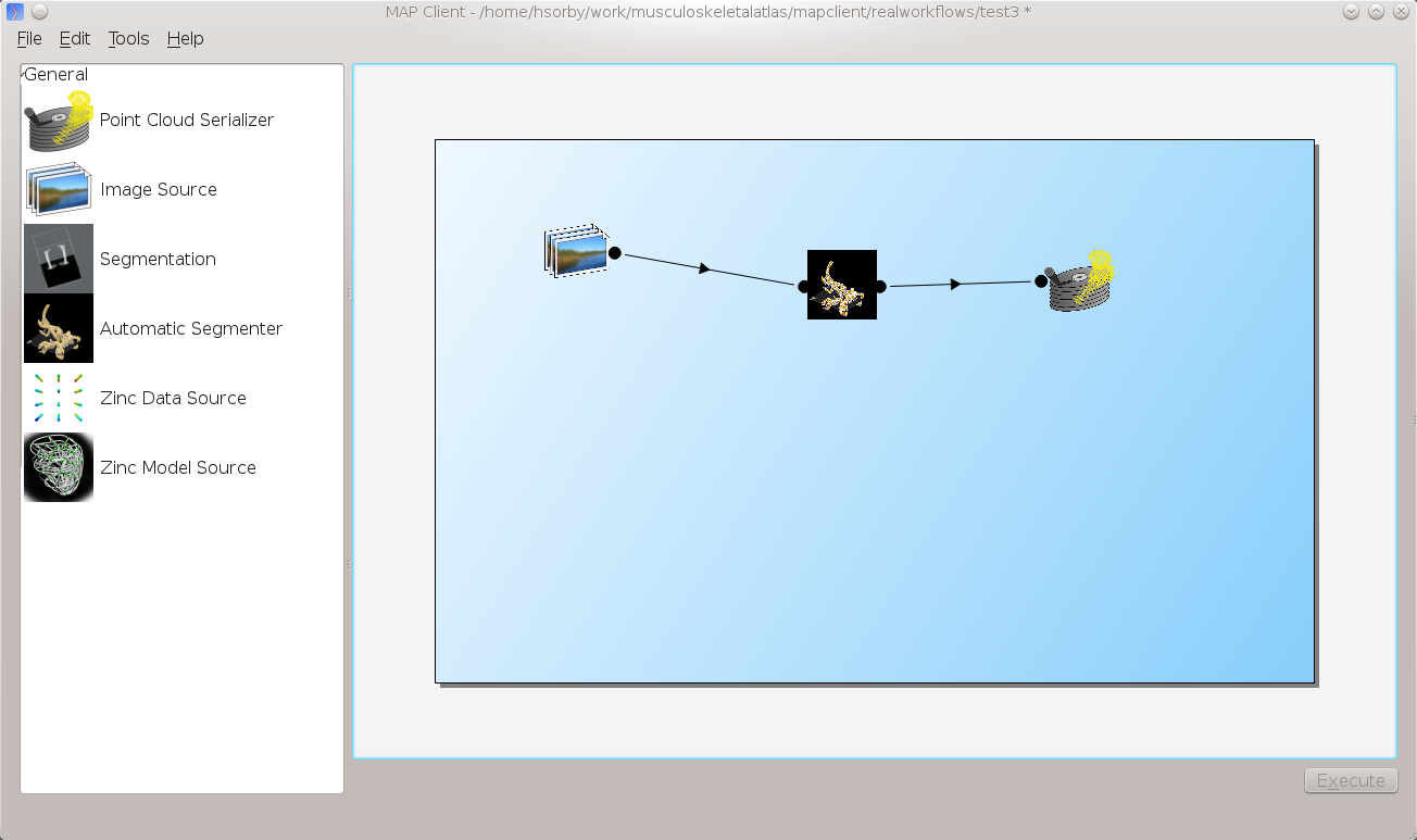
At this point you should have a workflow area looking like this:

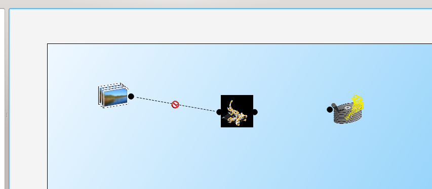
Once the All the steps in the workflow are configured (no more red cog icons) we can make connections between the steps. To make a connection between two steps the first step must provide what the second step uses. When trying to connect two steps that cannot be connected you will see a no entry icon over the connection for a short period of time and then the connection will be removed. The following image shows an incorrect connection trying to be made.
If the mouse is hovered over a port you will see a description of what the port provides or uses. To make a connection click on a port and drag the mouse to the port to be connected.
To execute the workflow we need to connect up the steps in the correct manner and save the workflow. The workflow should be connected up as can be seen in the following image.
Once the workflow has been saved the execute button in the lower left corner should become enabled. Clicking the execute button will, naturally enough, execute the workflow step by step.
Note
We can make connections between steps at anytime not just when all steps have been properly configured.
Automatic Segmenter Step
The 'Automatic Segmenter' actually allows us to interact with executing workflow. With this step we can move the image plane up and down and change the visibility of the graphical items in the scene. The image plane is moved through the use of the slider on the left hand side. The visibility of the graphical items is controlled by checking or unchecking the relevant check boxes.